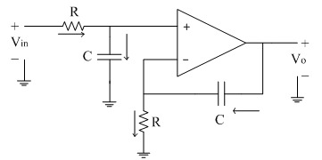
Here is a non-inverting op-amp integrator circuit (from https://www.electronics-tutorial.net/analog-integrated-circuits/op-amp-integrator/non-inverting-integrator/)
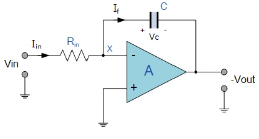
Here is an inverting op-amp integrator circuit (from https://www.electronics-tutorials.ws/opamp/opamp_6.html)
The non-inverting integrator circuit has several disadvantages compared to the inverting integrator, primarily due to differences in design, stability, and performance characteristics. Here’s a structured breakdown of the key disadvantages:
1. Complex Design and Stability Issues
- Feedback Configuration: The non-inverting integrator often involves capacitors in the feedback path connected to the non-inverting input, which can introduce positive feedback or destabilizing phase shifts if not carefully managed. This makes it prone to oscillation or instability, unlike the inverting configuration, which uses negative feedback more predictably.
- Design Complexity: Achieving a stable integrator function with non-inverting topology requires careful compensation and precise component selection, increasing design complexity.
2. Higher Sensitivity to DC Offsets
- No Virtual Ground: The inverting integrator benefits from a virtual ground at the inverting input (grounded through an input resistor), which isolates the input from DC offsets. In contrast, the non-inverting integrator directly connects the input signal to the non-inverting terminal, making it highly susceptible to DC offsets and input bias currents.
- DC Gain Issues: Without a feedback resistor across the capacitor (as is common in inverting configurations), the non-inverting integrator can integrate DC components, leading to output saturation unless compensated with additional resistors.
3. Noise and Stability Trade-offs
- Higher Noise Gain: In non-inverting configurations, the noise gain is typically higher than in inverting circuits. For example, if a capacitor replaces a resistor in feedback (e.g., Zf=1/(sC)Zf=1/(sC)), the noise gain at low frequencies could be significant, increasing output noise.
- Phase Shifts: The capacitive feedback in non-inverting integrators can introduce phase shifts that worsen stability, requiring additional compensation (like a resistor across the capacitor) to prevent oscillations.
4. Input Impedance and Loading Effects
- Lower Input Impedance for Non-Inverting Configurations: While the non-inverting input theoretically has high impedance, practical issues like feedback network interactions or improper grounding can reduce effective input impedance. This may not be ideal for driving sources with high output impedance.
- Signal Distortion: The lack of a virtual ground and potential loading effects could distort the input signal if not properly addressed.
5. Limited Frequency Response
- Poor Low-Frequency Performance: Non-inverting integrators are less effective at low frequencies due to their dependence on capacitive feedback, which has higher reactance (lower impedance) at lower frequencies. This can lead to reduced accuracy in integration.
- Bandwidth Limitations: The non-inverting configuration may have a narrower bandwidth compared to the inverting version, especially when using capacitors for feedback.
6. Practical Implementation Challenges
- Component Matching Requirements: Non-inverting integrators often require precise component matching (e.g., resistors and capacitors) to maintain stability and accuracy, which increases cost and complexity.
- Less Common Use Case: The inverting integrator is more widely used and well-documented, making it a more reliable choice for most applications.
Summary of Key Disadvantages
| Factor | Non-Inverting Integrator | Inverting Integrator |
|---|---|---|
| Stability | Prone to oscillation; complex compensation required | More stable with standard negative feedback. |
| DC Offset Handling | Sensitive to DC offsets and bias currents | Isolated via virtual ground (reduces DC sensitivity). |
| Noise | Higher noise gain due to feedback configuration | Lower noise gain (e.g., 1+Rf/Ri1+Rf/Ri) in standard designs. |
| Design Complexity | Requires careful compensation, less intuitive | Simpler, widely used, and easier to implement. |
| Frequency Response | Limited low-frequency performance; narrower bandwidth | Better frequency response with proper design. |
Conclusion
The non-inverting integrator is generally less practical than the inverting version due to its susceptibility to DC offsets, stability challenges, higher noise gain, and complex compensation needs. While it may offer specific advantages (e.g., phase alignment), these are often outweighed by the trade-offs in real-world applications. The inverting integrator remains the preferred choice for most integration tasks.
Leave a Reply